Ultrasound
This lesson covers:
- The high frequencies used in medical ultrasound imaging
- How the amount of wave reflection depends on acoustic impedance
- Advantages and disadvantages of ultrasound scanning
- The piezoelectric effect and its role in image production
- Why a coupling medium is needed
- Understanding A-scan range measurements
- Interpreting brightness variations in B-scan images
- Applying knowledge of the Doppler effect
Frequencies used in medical ultrasound
- Ultrasound for medical purposes employs longitudinal waves, characterised by frequencies above 20,000 Hz, which are out of the human hearing range.
- The frequencies for medical ultrasound typically span from 1 to 15 MHz.
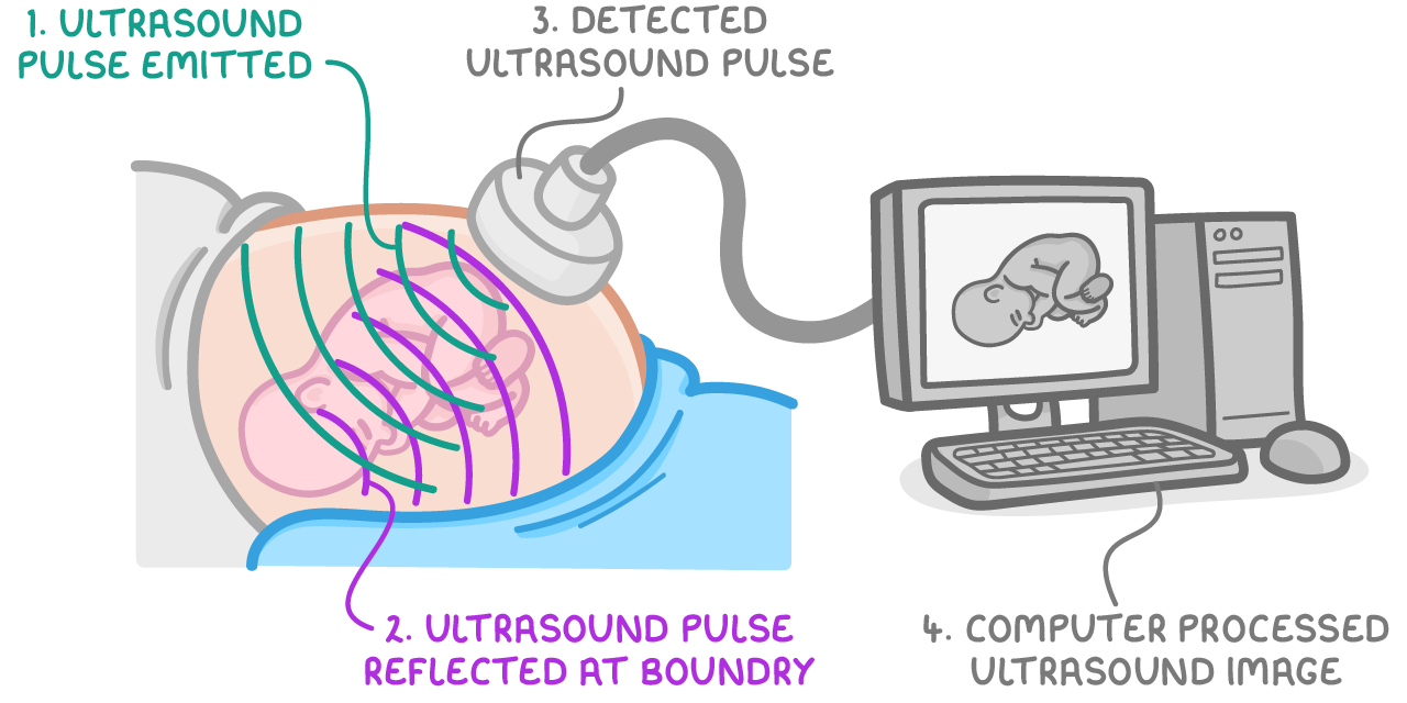
- Upon encountering a boundary between different materials, an ultrasound wave is subject to both reflection and refraction, the exception being when the wave hits at a direct 90° angle.
- It's the reflected waves that are utilised to create images.
Reflection and acoustic impedance
The acoustic impedance (Z) of a medium quantifies its resistance to the motion of longitudinal waves:
Z = ρc
Where:
- Z = acoustic impedance (kg m−2 s−1)
- ρ = density of the medium (kg m−3)
- c = speed of sound within the medium (m s−1)
When an ultrasound wave travelling in one medium with impedance Z encounters a boundary with another medium of impedance Z', the following occurs:
- A significant difference between Z and Z' results in greater reflection.
- Identical impedance values mean no reflection occurs.
The ratio of reflected intensity (Ir) to incident intensity (I) is calculated as:
IIr=(Z2+Z1)2(Z2−Z1)2
Where:
- Ir = reflected intensity (W m-2)
- I = incident intensity (W m-2)
- Z2 = acoustic impedance of material 2 (kg m-2 s-1)
- Z1 = acoustic impedance of material 1 (kg m-2 s-1)
Worked Example - Calculating the reflection intensity
Calculate the ratio of reflection intensity when an ultrasound wave travels from tissue with an acoustic impedance of 1.6×10⁶ kg m-2s-1 to bone with an impedance of 3.8×10⁶ kg m-2s-1.
Step 1: Formula
IIr=(Z2+Z1)2(Z2−Z1)2
Step 2: Substitution and correct evaluation
IIr=(1.6×10⁶+3.8×10⁶)2(1.6×10⁶−3.8×10⁶)2=0.166
This reflection intensity ratio of 0.166 signifies that 16.6% of the incident ultrasound intensity is reflected back at the interface between tissue and bone.
Advantages and disadvantages of ultrasound
Advantages
- Safe as it doesn't expose patients to ionising radiation
- Capable of real-time imaging of soft tissues
- Economical and portable
- Allows for patient movement during fast scans
Disadvantages
- Inability to penetrate bone
- Imaging is obstructed by air gaps
- Provides limited detail for solid masses
- Lacks capability for analysing detected masses
The Piezoelectric effect
Piezoelectric crystals:
- Produce an electric potential when compressed or stretched, due to charge displacement
- Change shape upon application of voltage
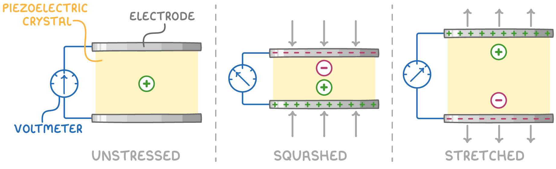
These crystals function as receivers of ultrasound waves, converting the generated voltage into images.
Requiring an Imaging coupling material
- Air's acoustic properties vastly differ from those of body
tissue, leading to nearly complete reflection of ultrasound at the body surface without a coupling material.
- Gels serve as coupling material by displacing air and matching the impedance of tissue, facilitating effective ultrasound transmission.
A-Scan Range Measurement
In A-scan ultrasound:
- Emits short pulses synchronised with a sweep of the CRO electron beam.
- Reflections from within the body appear as vertical deflections on the CRO.
- Incorporates time-gain compensation to amplify signals arriving later and weaker.
- The horizontal sweep of the beam correlates with the time-of-flight, enabling distance measurements within the body.
- A sequence of pulses generates a comprehensive image.
B-Scan brightness variations
For B-scans:
- The electron beam's downward sweep generates 2D images.
- Variations in pulse amplitude determine the brightness of the display.
- A transducer array facilitates the scanning process.