Resistance In Series & Parallel
This lesson covers:
- The principle of conservation of charge in electrical circuits
- Kirchhoff's First Law, which is related to the conservation of charge
- The principle of conservation of energy in electrical circuits
- Kirchhoff's Second Law, which is related to the conservation of energy
- The application of Kirchhoff's Laws in analysing combinations of resistors
Conservation of Charge
In electrical circuits, charge is always conserved. This implies:
- Charge is not consumed or lost as it circulates through a circuit.
- At any junction within the circuit, the amount of charge entering is equal to the amount of charge exiting.
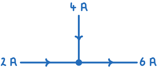
Since current is defined as the flow rate of charge, the current entering a junction is always equal to the current leaving that junction.
Kirchhoff's First Law clearly states:
'The sum of currents entering a junction is equal to the sum of currents leaving that junction.'
Conservation of energy
Energy, like charge, is always conserved in electrical circuits. This means in any closed loop:
- The energy input is equal to the energy output.
- The total electromotive force (e.m.f.) supplied is equal to the total of all potential differences (p.d.s) across each component in the loop.
This is the basis of Kirchhoff's Second Law:
'The total e.m.f. in a closed loop is equal to the sum of potential differences across each component in that loop.'
Expressed in a formula, it looks like this:
∑ E =∑ I R
Applying Kirchhoff's laws
In exams, questions often present incomplete data about circuits, requiring the use of Kirchhoff's Laws to find solutions. The key principles for different circuit configurations are below.
Series Circuits
- The current is the same through all parts of the circuit.
- The electromotive force (e.m.f.) is divided among the components based on the formula V = IR.
- The total resistance (R) is the sum of all individual resistances in the circuit.
Rtotal = R1+R2+...+Rn
Where:
Rtotal = total resistance of the network of resistors (Ω)
R1 = resistance of resistor 1 (Ω)
R2 = resistance of resistor 2 (Ω)
Rn = resistance of nth resistor (Ω)
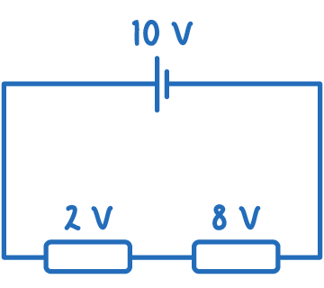
Worked example - Using kirchhoff's laws in a series circuit
Consider a series circuit with two resistors, R1 = 4 Ω and R2 = 6 Ω, and a battery supplying an e.m.f. of 10 V. We need to calculate the current in the circuit and the potential difference across each resistor.
Step 1: Calculate Total Resistance
Rtotal = R1 + R2 = 4 Ω + 6 Ω = 10 Ω
Step 2: Calculate Current
I = RV = 1010 = 1 A
Step 3: Calculate Potential Difference Across Each Resistor
Potential difference for R1:
V1=I×R1=1×4=4V
Potential difference for R2:
V2=I×R2=1×6=6V
Parallel circuits
- The total current is the sum of the currents in each branch.
- The same potential difference is present across all components.
- The total voltage (V) is equal across all branches.
The total resistance can be calculated using:
Rtotal1=R11+R21+...+Rn1
Where:
Rtotal = total resistance of parallel network of resistors (Ω)
R1 = resistance of R1 (Ω)
R2 = resistance of R2 (Ω)
Rn = resistance of nth resistor (Ω)