I-V Characteristics
This lesson covers:
- How to experimentally obtain an current-voltage (I-V) characteristic
- I-V characteristics in various components such as resistors, filament lamps, diodes
- The impact of temperature on the resistivity in metals and filament lamps
Understanding I-V graphs
The term "I-V characteristic" represents a graphical relationship between the electric current (I) flowing through a component and the voltage (V) applied across it.
Key points:
- A straight graph line signals a consistent resistance.
- A curved graph line indicates a varying resistance.
Steps to create an I-V graph:
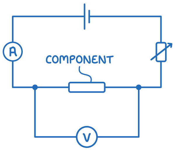
- Set up a circuit with a variable resistor in series with the component and power supply.
- Record the voltage and current values displayed by the voltmeter and ammeter respectively.
- vary the resistance of the variable resistor.
- Record the new current and voltage values.
- Repeat steps 3 and 4 until a full set of readings is obtained.
- Plot these values to show current (I) against voltage (V).
- Draw a line of best fit.
Resistor I-V characteristic
Ohmic conductors, like metals and resistors, abide by Ohm's law, particularly at a steady temperature, resulting in a linear I-V graph which implies a uniform resistance.
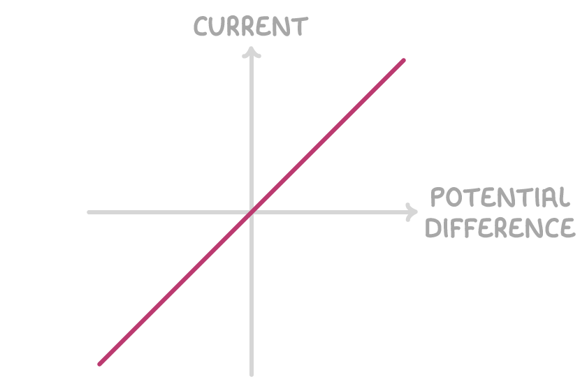
Characteristics of ohmic materials:
- Direct proportionality between current and potential difference.
- Constant resistance when the temperature remains stable.
- The steeper the gradient, the lower the resistance.
I-V Graphs in Filament Lamps
The graph below shows the I-V graph obtained for a filament lamp.
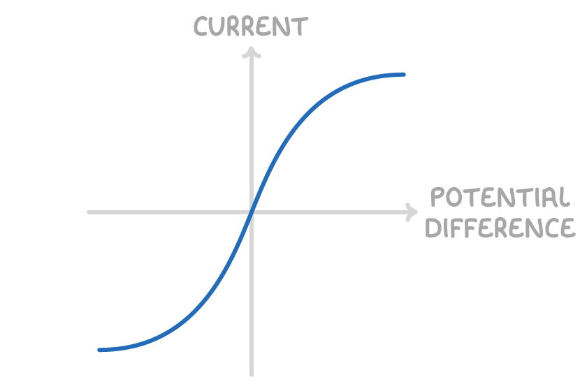
Filaments are thin coils of wire. When a current flows a filament the temperature increases.
As the filament temperature increases:
- Positive ions in the metal vibrate more vigorously.
- This results in more collisions for electrons.
- Electron movement becomes more challenging.
- Consequently, the electrical resistivity of the filament increases (shown by a decreasing gradient on the I-V graph).
Diode I-V characteristics
Diodes, including LEDs, are unique in that they conduct current primarily in one direction, known as the forward bias.
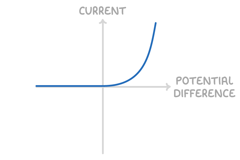
When the voltage across the diode is negative:
- The resistance is extremely high.
- The current is almost negligible.
When the potential difference across the diode is positive:
- Resistance drops significantly above a threshold of approximately 0.6V.
- Beyond this threshold potential difference, the current flow increases rapidly.