The A.C. Generator
This lesson covers:
- Understanding how alternators generate alternating current
- Faraday's law of induction and its application in a rotating coil
- Calculating the induced electromotive force (e.m.f) in a rotating coil through flux linkage
- The relationship between angular velocity, magnetic flux density, and induced e.m.f.
Alternators generate alternating current
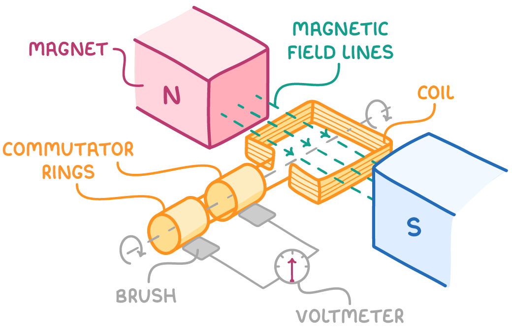
Generators, also known as dynamos, transform kinetic energy into electrical energy by spinning a coil within a magnetic field. This movement creates an electric current via a phenomenon known as electromagnetic induction.
Alternators are a specific kind of generator that produce alternating current (AC). They do this by continuously rotating a coil inside a magnetic field.
The voltage and current output alternate between positive and negative values with every half turn of the coil, producing the oscillating waveform that is characteristic of AC power.
Induced e.m.f through one rotation
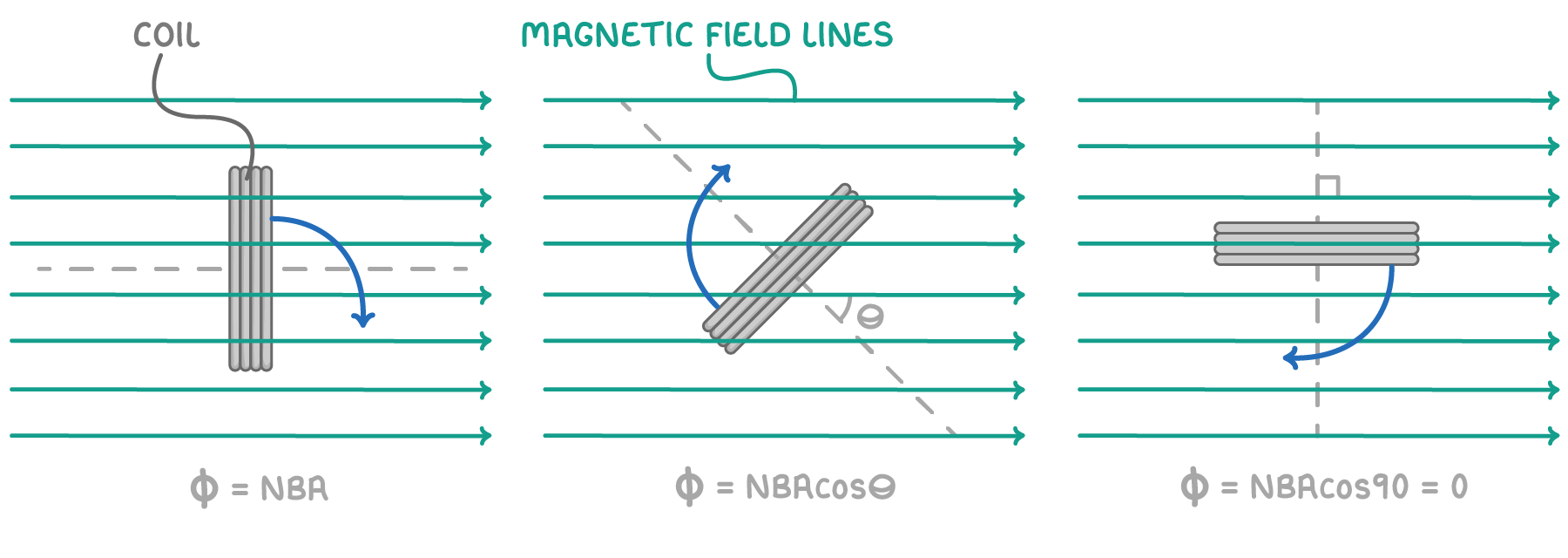
As the coil rotates the flux linkage in the coil is constantly changing.
Where:
ϕ = flux linkage (Wb)
N = number of turns
B = magnetic flux density (T)
A = area of coil (m2)
θ = angle between field lines and normal of the coil (°)
Key points:
- The flux linkage is greatest when the normal of the coil is parallel to the magnetic field lines. ϕ =N B A
- The flux linkage is zero when the normal of the coil is perpendicular to the magnetic field lines.
- The induced e.m.f. is maximum when the rate of change of magnetic flux is greatest.
Calculating Induced e.m.f
The induced e.m.f (e) can be calculated using Faraday's law:
ϵ=−ΔtΔΦ
For a rotating coil, this becomes:
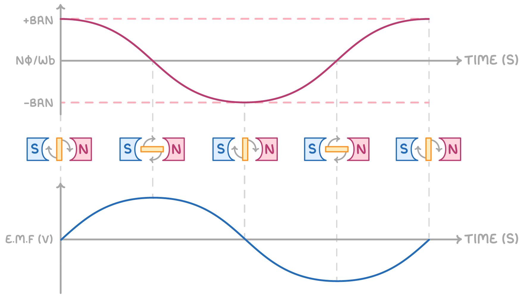
Φ=BANcos(ωt)
Therefore:
ϵ=−NBAωsin(ωt)
Where:
- ϵ = Induced e.m.f (V)
- ω = angular velocity (rad s-1)
This means the output e.m.f varies in a sinusoidal manner, peaking when the coil is parallel to the magnetic field and dropping to zero when it is perpendicular.
Worked example: - Calculating induced e.m.f in a rotating coil
A coil with 50 turns, an area of 0.1 m2, rotates in a magnetic field of 0.5 Tesla at an angular velocity of 300 rad s-1. Calculate the maximum induced e.m.f.
Step 1: Formula for induced e.m.f
ϵ= −N B A ωsin(ωt)
Step 2: Substitution and correct evaluation
The maximum e.m.f occurs when the value of sin(ω t)= 1
ϵ=NBAω=50×0.5×0.1×300=750V
Relationship between angular velocity, flux density and induced e.m.f
The peak induced e.m.f is influenced by:
- Angular velocity (ω) - Quicker rotation speeds up the flux cutting, enhancing the rate of change in flux linkage.
- Flux density (B) - A stronger magnetic field increases the flux linkage.
- Coil parameters (N, A) - A greater number of turns and a larger coil area result in higher flux linkage.
Therefore, to maximise the power output of an alternator, engineers strive to optimise these parameters efficiently.