Electromotive Force & Internal Resistance
This lesson covers:
- Understanding internal resistance in batteries and its causes
- The concepts of electromotive force (EMF), terminal potential difference (PD), and lost volts
- Applying the relationship between EMF, current, and internal resistance in practical calculations
- Conducting an experimental investigation to understand EMF and internal resistance
Understanding internal resistance and its impact
Every battery or cell has an inherent internal resistance, often denoted as (r). This resistance is primarily caused by the movement of electrons through the material of the battery, which leads to collisions and consequently energy loss. The electromotive force of the cell is denoted as (E).
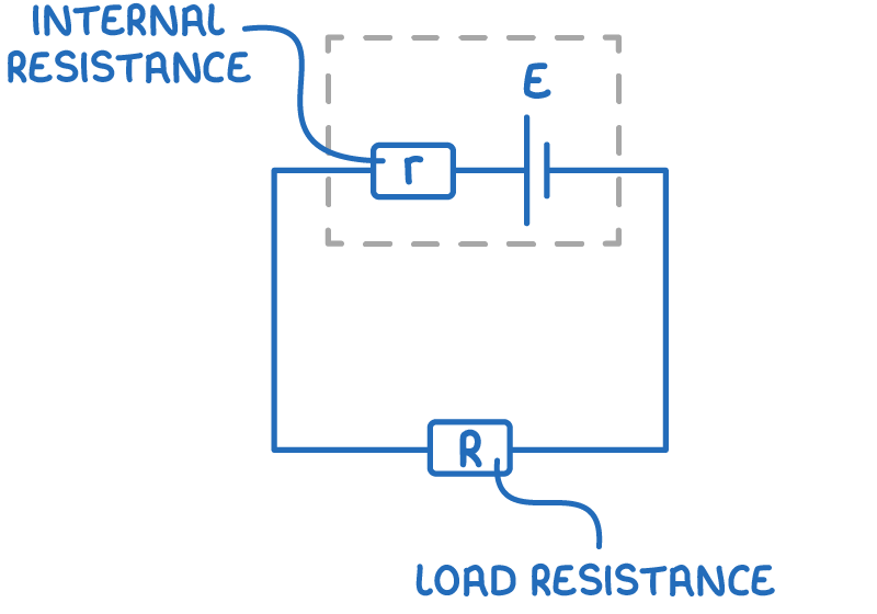
This internal resistance is responsible for the conversion of some electrical energy into heat, which can warm up the battery. The total resistance outside the battery, which the battery serves, is termed the load resistance (R).
Key Definitions
Electromotive force (E):
The electromotive force (emf) of a battery is the total energy provided per unit charge by it, measured in volts.
Terminal potential difference (V):
The terminal potential difference (V) is the energy per unit charge utilised in the external circuit, measured in volts.
Lost volts (v):
Ideally, without any internal resistance, the terminal potential would equal the emf (E). However, the presence of internal resistance (r) leads to a loss of energy per unit charge, known as the lost volts (v).
The principle of conservation of energy gives us the equation:
E = V + v
The current is the same at all points in a series circuit so the current flowing through the internal resistance (r) is the same as the current flowing through the load resistance (R). Combining the equation above with Ohm's law gives:
E=IR+Ir=I(R+r)
Note: when there is no current flowing through the internal resistance, there is no lost volts. With no current flowing, a voltmeter in parallel with the cell will read the emf.
Calculating total emf and terminal potential difference
For cells in series:
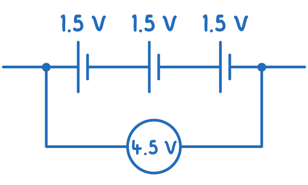
Etotal=E1+E2+...+En
In a series configuration, the EMF of each cell adds together because each cell contributes to 'pushing' the charges.
For cells in parallel:
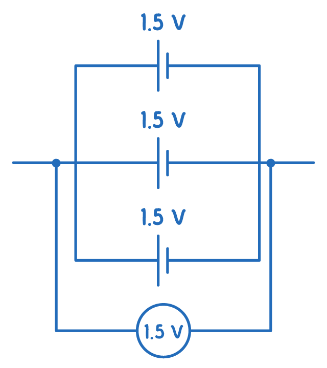
Etotal=E1=E2=...=En
When identical cells are connected in parallel, the current divides evenly among them.
Worked example - Parallel circuit calculations
Consider a circuit consisting of three identical batteries connected in parallel, each with an emf of 1.5 V and an internal resistance of 0.5 Ω. The total current flowing through the circuit is 6 A.
Determine the total EMF, internal resistance, and terminal potential difference of the circuit.
Step 1: Determine total EMF
All three cells are in parallel, therefore the total emf is the same as the individual emfs.
Total emf = 1.5 V
Step 2: Calculate the total internal resistance
rtotal1=r1+r1+r1=0.51+0.51+0.51=6
rtotal=61 Ω
Step 3: Calculate lost volts:
v=Ir
v=6×61=1V
Step 4: Calculate terminal potential difference
V = E − v
V = 1.5 − 1 = 0.5 V
Experimental investigation into emf and internal resistance
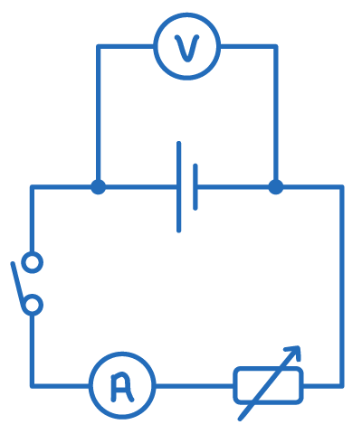
- Set up a circuit with a cell, variable resistor, switch and ammeter in series. Connect a voltmeter in parallel to the cell.
- With the switch open, record the emf of the cell from the voltmeter.
- Close the switch and record the values of current and terminal potential from the ammeter and voltmeter respectively.
- Vary the resistance of the variable resistor and record the new values of current and terminal potential.
- Repeat step 4 until at least 8 readings have been obtained.
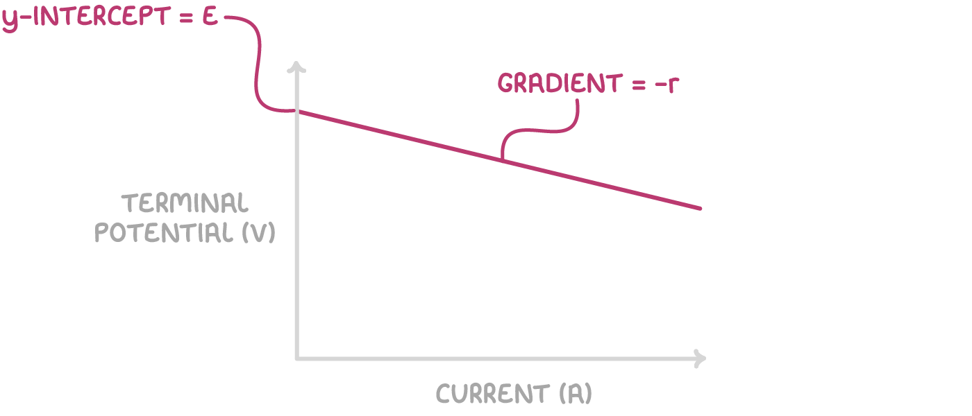
- Plot a graph of current on the x-axis against terminal potential on the y-axis.
- The gradient of the graph is equal to -r.
- The y-intercept represents the emf of the cell.