The Operation Of A Transformer
This lesson covers:
- How transformers use electromagnetic induction to change AC voltages
- The role of primary and secondary coils wound around an iron core
- Calculating induced electromotive force (e.m.f.) using Faraday's and Lenz's laws
- Step-up and step-down transformers and their turns ratio
- Real-world applications of transformers
Transformers and electromagnetic induction
Transformers are devices that can either increase (step up) or decrease (step down) the alternating voltages in an electric circuit, employing the principle of electromagnetic induction. They are composed of two coils of insulated wire (referred
to as the primary and secondary coils) coiled around a core made of iron.
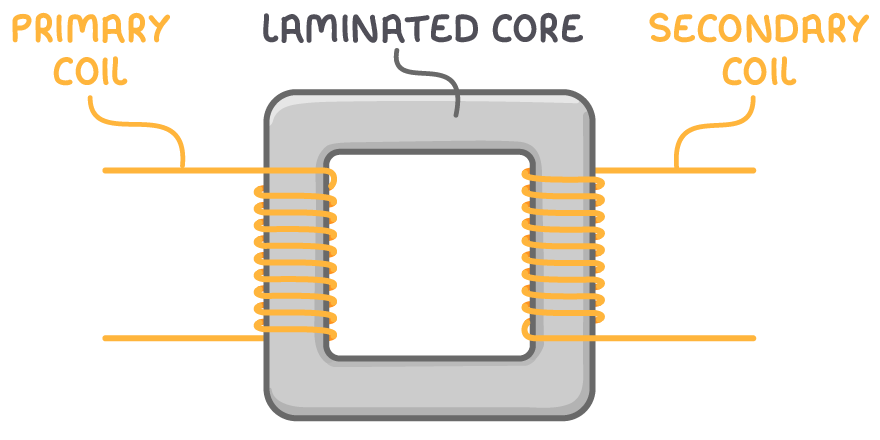
When an alternating current flows through the primary coil, it induces a changing magnetic flux within the iron core. This fluctuating magnetic flux, in turn, traverses the secondary coil, inducing an electromotive force (e.m.f.) in the secondary coil.
Calculating induced E.M.F. using Faraday's law
Faraday's law of electromagnetic induction reveals that the magnitude of the induced e.m.f. in a coil is directly proportional to the rate of change of magnetic flux linkage it experiences.
For the primary coil:
Vp=−NpΔtΔϕ
And for the secondary coil:
Vs=−NsΔtΔϕ
Where:
- Vp = voltage across primary coil (V)
- Vs = induced voltage across the secondary coil (V)
- Np = number of turns on the primary coil
- Ns = number of turns on the secondary coil
- ΔtΔϕ = rate of change of magnetic flux through the coils (Wb s-1)
These two equations can be combined to give the transformer turns ratio:
NsNp=VsVp
Worked example - Calculating transformer output voltage
Consider a transformer with 120 turns on its primary coil and 350 turns on its secondary coil. If the input voltage is 230 V, what is the output voltage?
Step 1: Formula
VpVs=NpNs
Step 2: Substitution and correct evaluation
Vs=Vp×NpNs=230×120350=670.83V
Transformer efficiency
In an ideal transformer, where maximum power transfer is achieved:
PIN=POUT=VpIp=VsIs
Key points:
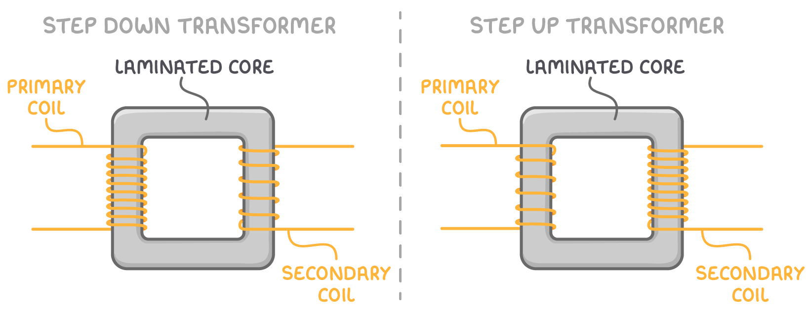
- If Ns > Np, the transformer functions to step up the voltage and decreases the current.
- If Ns < Np, it serves to step down the voltage and increase the current.
The ratio of turns between the secondary and primary coils thus determines the transformer's operational nature. It's important to note that actual transformers exhibit some loss and do not achieve 100% efficiency.
Transformer efficiency is given by:
efficiency = IpVpIsVs
Applications of Transformers
Electrical power transmission:
- Employing high voltages is an effective strategy to minimise power losses in transmission cables.
- High voltage transmission reduces the current in the transmission lines and thereby reduces the heating effect in the wires.
- Grid transformers at power stations step up the voltage for efficient transmission.
- Local substations then step down the voltage to levels suitable for household and commercial use.
Electronic devices:
- The majority of electronic devices operate on voltages below 20 V.
- Device chargers incorporate small transformers to adapt the mains voltage to lower levels required for device operation.