Fleming's Left Hand rule
This lesson covers:
- Understanding Fleming's left-hand rule for current, magnetic field, and motion
- How the force on a conductor depends on magnetic flux density
- The relationship between current, field strength, wire length, and force
- Explaining how the force varies with the angle between current and field
Fleming's Left-Hand Rule
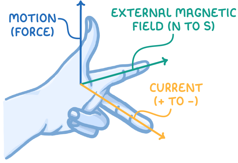
When an electric current flows perpendicular to the magnetic field lines in a uniform external magnetic field, it experiences a force. Fleming's left-hand rule helps determine the direction of this force:
- First finger - External magnetic field direction
- Second finger - Current direction
- Thumb - Force/motion direction
So if the thumb points upwards, that is the direction the wire segment will move.
Force depends on magnetic flux density
The force experienced by the wire segment is proportional to the magnetic flux density (B) of the external field.
For a wire perpendicular to the field, the force is given by:
F = B I l
Where:
- B = magnetic flux density (T)
- I = current (A)
- l = length of conductor (m)
Worked example - Calculating the force on a wire in a magnetic field
A wire carries a current of 5 A and is placed within a uniform magnetic field of 0.2 T. The wire is perpendicular to the magnetic field and has a length of 2 meters. Calculate the force exerted on the wire by the magnetic field.
Step 1: Formula
F = B I l
Step 2: Substitution and correct evaluation
F=0.2×5×2=2 N
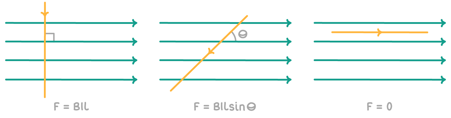
Angular dependence of force
The force reaches its maximum when the wire segment is perpendicular (90°) to the field lines. At other angles, the component of the magnetic field perpendicular to current gets reduced, and hence force decreases.
The relationship is:
F = B I l sinθ
Where:
F = force (N)
B = magnetic flux density (T)
I = current (A)
l = length of conductor (m)
θ = angle between the field and wire segment (°)
Examples: